The Design Of The Das D-9 Hawk Moth
This is a condensed version of the winning submission to the Royal Aeronautical Society Light Aircraft Design Contest 2023 - The Das D-9 Hawkmoth by Prasenjit and Prodyut Das
Introduction
It is almost an axiom that to follow the
specifications exactly is a recipe for getting into trouble and it is better to
work out a common-sense interpretation of what is meant rather than what is written
down. The competition rules calls for an aircraft capable of flying the given
pattern and there is an implied anxiety that somehow the aircraft would “run
out” of battery power before it could complete the pattern. This had us worried
when we found after the rough first designs that the aircraft could fly the
pattern with energy enough to spare and we then reassured ourselves that it was
more an explanation of the way the marks would be allotted in case power
running out happened. The +6g/-3g stress limits of the design reassured us that
we were not expected to design an unlimited class of aerobatic aircraft which
frankly is NOT sports flying and with 12 g stress limits, use of composites and
installation of ejection seats (Su-31 etc.) the competence and resources
for which would be at the corporate or national level and we considered well
beyond the technical skills and the sense of fun in participating in
this competition.
Talking about fun we must begin by thanking the
R.Ae.S., as an old Mechanical engineer and a young Software engineer id est -
no aeronautical training we had a great deal of fun from the pleasant feeling
of weighty importance and wisdom (said he cautiously!) as the
team discussed, usually without too much physical violence, conflicting
opinions on stressing, 63 series aerofoils, or the effect of Reynolds number or
the vortices likely to be shed by the big canopy and how it would affect the
fin and whether it would jettison cleanly without knocking off the fin and
similar such charivari.
What therefore began to germinate from the first
paragraph was something along the lines of the great aerobatic trainers of the
past. Capable of flying the full repertoire -or near abouts- of conventional
aerobatics and yet handling pleasantly enough for the tyro to be not only not
intimidated by the aircraft but also actually entice many to acquire a taste
for aerobatic flying.
There is a perennial and unresolved debate about
whether the trainer should be easy or difficult to fly with a supposed golden
norm of “easy to fly but difficult to fly well” It would require considerable
actual hard-earned experience, perhaps natural to fabled designers like Bishop,
Hagg or Sir Geoffery of De Havilland’s to be able from ab initio design that
quality of flying into a new aircraft. Lacking that experience we felt that the
best would be to a design that should capable of being “tweaked” easily to have
the desired flying characteristics without requiring major re-manufacturing
effort.
The rules do mention something about training and
modestly doubting one’s real Intelligence, the Artificial Intelligence approach
of key words - Fully Aerobatic, Training, International Competition and
Electric Power were taken to be the key deciders for the design. These
attributes were grafted on a base of the usual design criteria, custom, superstition,
old wives’ tales of sturdiness, simplicity, low project financial inertia by
which we mean that there must always be hope that the prototype may be actually
built. It is unfortunate that the final decider of a design’s future is the Banker’s
point of view, too often not an aviation enthusiast, too often not sensitive to
the need to progress electric aviation but quite sensitive to financial risks.
A brilliant design is as doomed as a bad design if it requires funds that are
beyond normal expectations. The attempt at achieving the “best” is to be
checked and resisted especially if it requires much technology, finance, or
management; it is sufficient to attempt second best if not the third - we quote
of course Dr. Watson Watts whose Radar was inferior to the Germans (do we
commit blasphemy!?) but it was ready, could be manufactured and operated
without complex interactions from existing resource and, finally, seems to have
done the job. Many of the other things we mentioned in our 2022 entry - the Das
D-8 Zanonia e.g., the “boundary layer” in aeronautical progress, the required
suspicion of the latest that the costermonger are hawking, the importance of
paying obeisance to old wives’ tales and superstitions we will not re-elaborate
here but they continue to guide our thinking.
Aircraft design starts with a series of vague often
contradictory pipe dreams; in a domestic washing machine it is called “fuzzy
logic.” Below is listed an incomplete and somewhat random collection of
contradictory ideas that somehow shaped the design. With diffidence we write
down what we felt the ideas to be important “shapers” of the design and should
be seen as a confession of culpability rather than as a confident declaration
of Quad Erat Demonstrandum!
The need for caution
- When R/C controlled electric flight came to the world of Aeromodelling many modelers took to equipping tried and tested Free Flight designs - Vic Smeed’s “Tomboy” of old Aeromodeller’s Plan Services - which was quite popular in India - and launched themselves into the world of electric free flight by replacing the trusty old Mills 0.75 with a Mabuchi or Extraa. As an approach to design, even in the world of full scale or real-life design such an approach is based on sound realities and practical common sense - do not try too many new things- electric motors, lithium batteries, along with a new airframe all at one go.
- Such caution can be seen even in the full-scale electric aircraft currently flying. The Cranfield University technology demonstrator which appears as if it is built from leftovers from a 1930s aeronautical hangar sale, is in terms of airframe and aerodynamics very timid but it is astute because the focus is on uncovering the unknown problems of the new technology rather than having the team struggle with the taming of the spin characteristics of an efficient but highly loaded tapered wing at approach speeds.
- The above ideas nudge us to think that whilst the “latest and the best” pitch of the universal (Technological) costermonger has its attractions, for those with limited development resources there may be benefits of looking at designs of yesteryears to see how much of their wisdom could be re-used because they were excellent engineers limited too often only by their resources rather than by intelligence, wisdom & vision. To illustrate my poser: - Given the limited finance and time constraints that Lindberg faced in 1927, what changes could we (even with our present-day knowledge) make to The Spirit of St. Louis? Perhaps a Townend ring, if that? A prototype variable pitch propeller’s reliability would be a question and could Lindbergh have got a flapped laminar flow cantilever wing off the ground that muddy morning even if he had managed to design, build, and test it in time? The results would be marginally better but the risks would be appalling, and with hindsight, the simpler “cruder” solution worked!
Copying
as an Engineering skill
An engineer who will not look around to see what has
already been done is not only going to do a lot of unnecessary work and
mistakes but also can be thought of as an arrogant fool. There is a great deal
of unthinking pejorative connotations associated with copying but this is
usually an unfortunate knee jerk reaction. Designing something that looks like
an existing product is quite different from engineering that something. Even a
case of actual and direct copying (TU-4 from B-29) there is much engineering
skills to grudgingly admire. There is no dishonour in looking around, thinking,
and then looking around some more again, backed by some quick back of the
envelope calculations, in the search for the best feasible minimum solutions.
An engineer is employed to make money for his employer. If we subscribe to that
adage that an engineer is someone who does for six pence what any fool can do
for six shillings then, copying
and its possibilities and its pitfalls is something that needs to be taught
formally as a design technique.
Looking at the past may look like copying has an
illogically pejorative stigma, we say that though the muse was the Jungmeister
the final product being a side by side two seat sesquiplane with a streamlined
nose is even less a copy of the Jungmeister than the Bolkow Junior is a copy of
the Wittman Tailwind. We do not know if Bjorn Andreasson had a good look at the
Wittman Tailwind or not, but even if he had the Wittman drawings right under
his tracing sheet, we will say it was still a masterly conformal transformation
of the design from wood and steel tube to sheet metal construction with special
skill being displayed in the matter of designing the pilot entry and egress for
such a sheet metal fuselage.

The
peculiarities of Electric Flight
At the first puff, the pipe dreaming engineer’s
dream of electric flight is not very encouraging. For example, an 85-kW modern
engine i.e., Rotax 914 UL with an hour’s fuel will weigh about 100 kgs.
increasing to 140 kgs if we wanted a direct drive 105 HP Hirth 504 old technology
engines. This compares with 260 kilos of a modern electric drive for fulfilling
the same function i.e., changing chemical energy into usable torque for a given
period. The differences in weight goes up by about 160 kg/hr for every further
hour of endurance. The figures indicates that the plague of early aviation, heavy
propulsion systems, have come back to haunt us and copying or resurrecting appropriate
ancient aeronautical spells and exorcism may be in order.
Electric flight has its
handicaps but one must think of the transition from IC power to electric rather
in the same spirit and terms of designing and converting a component into plastic
from what was originally in metal. There are disadvantages with electric
propulsion but equally there are advantages which the canny designer can glean
from a field of technical stubble.
A list of differences
both good and adverse, not arranged in order of importance, which the pipe
dreaming engineer must keep in mind would read something like this:
- Much lower gyroscopic moments of the engine propeller combination compared to IC engines, and we are not even thinking of the Rotaries! This is an almost revolutionary important feature for an aerobatic aircraft that is not available to the designer of aircraft with the current IC power plant and will greatly affect fine tuning of handling as well as empennage sizing. Of course, there will be those who will say that stick and rudder work required to manage gyroscopic effects was all that was in aerobatic flying but today’s young teenager will have to grow old in aerobatics before he too will join in the grumble.
- Cooling drag of IC engines can be as high as thirty percent of the total drag of the airplane. Electric flight offers considerable reduction in the total drag thus making usually draggy configurations such as the biplane quite feasible. Just think of the Jungmeister’s Simens Halske radial with the Emrax installations. The more compact motor means cutting down the size of the cowling improving visibility and reducing drag.
- Since the weight of the battery is very large i.e., it is the heaviest single item, by locating this on the CG, one can reduce the inertias on the yaw and pitch axis. In conventional IC power the engine has perforce (Bell P-39 Airacobra excepted) be located at one extremity of the aircraft playing havoc with inertias in the yaw and pitch. This is a new possibility in the design of aerobatic aircraft which is not available with conventional power. In extremis the entire powertrain including the motor can be located at the CG resulting in in yaw and pitch inertias unachievable with conventional power aircraft designs but this would require a lightweight Cardan shaft of composite construction. Whilst we were enticed by this idea, in following the “mantra” of third best first we have kept a totally centralized “Ultra Camel” or Westland F 7/30 concept for the future Mk2.
- In an electric powered aircraft, the CG shift due to energy burn does not occur and a smaller stability margin is of no consequence.
- At a second order the lack of vibration and noise will make for a quieter training environment and theoretically if not in practice is that vibration related stress and fatigue of the airframe would be lower.
- Apart from the difference in weight and bulk of the energy conversion system already mentioned above there is also the difference in energy density and the ease of replenishment. The 18 litres or so fuel can be stored in relatively light tanks and refilled with a nozzle whereas the battery requires both bulk and weight. However, it takes some thinking for us who grew up in the lead acid era that LI-PO is much lighter density wise than Pb-Acid! Nevertheless, battery safety and handling during recharge/ replacement are important new design area.
- The location of the heavy battery behind the pilots may need appropriate structural design so that the pilots are not crushed by the weight of the cells in case of a crash landing.
- Unlike a reciprocating engine that gives useful torque over a very limited range of speed often enforcing the usage of variable pith propellers the electric motor allows much wider speeds and torques. A variable pitch propeller is not sine qua non.
- A heavy propulsion system with a low power to weight ratio requires optimization of structural efficiency even at the expense of aerodynamic efficiency. At the kind of speeds, we will be looking at, structural efficiency would take precedence over aerodynamics
Surprise
It came as a surprise to that aerobatic aircraft do
not fly the course as much as they obey the “Dynamics of a Particle” (a text
book on the subject dating back to 1903 by S. Loney that was required reading
in our first year Ug! Ugh!). This emphasis on particle dynamics approach
explains the present trend to low drag high speed monoplanes such as the
Cranfield A1 and the various models of Extra. Our approach was that the power
to weight ratios of current generation of electric powerplants do not allow us
to take on such expert machines as the Su-31 head on. It would be sufficient if
we create a very good handling trainer capable by its safety, performance, and
predictable good behaviour of encouraging, indeed enticing the young, novice
pilot to get into aerobatic flying and yet like the Klemm Super Akrobat did at
the Hulavington Champoinship in 1985 do respectably well Championships.
The
Evolution of the Design
“The
aircraft was a copy of all the aircraft that went before it”. This post war remark, possibly said with
polite Japanese testiness, is ascribed to Jiro Hirokoshi, the Chief Designer of
the legendary Mitsubishi Zero. Personally, we think the Zero looked like a
Gloster F.5/34 but that it is not to suggest that the Zero was a copy of the
Gloster any more than the Percival Provost (the piston one) was, barring the
roundels, a copy of some pre-war Japanese design. In our case the muse (if that
is the word), was the Bucker JungMeister single seat aerobatic aircraft. We
have not had the pleasure of seeing one in corpo vivo but You Tube gave
us an indication of its fabled performance and it enthralled. Though the
handicap of drag in aerobatics warned us against the biplane we were simply
charmed by that visual combination of the power, ugliness, and fragility. The
Jungmeister had the clutter of a Continental Locomotive with the fairy
daintiness of fabric covered biplane wings and of course the hawk like swoop of
its undercarriage. It looked like a
Henschel or Borsig Tank locomotive with wings! We were charmed and found
ourselves looking for reasons “to have a biplane” Design has an element of
illogic or is passion a kinder word?
The other contender muse was the single Skoda Kauba V4 monoplane which had fascinated the older team member ever since it appeared in the December 1965 issue of FRI. We explored it but with regret chose the biplane as the better.
The choice of a biplane from a century ago over a monoplane requires careful reasoned explanation and below is the attempt:
- The biplane is misunderstood and misjudged. The performance of a biplane is usually compared with a monoplane of similar power but perhaps half the wing area and a snap judgment made that the biplane is an inefficient layout. This is prejudice. The biplane does have two addition wing roots and the interference drag is higher but that is partly offset by the lighter structural weight, as much as 50% lighter in some cases. One should remember that the Fiat CR42 Falco with a DB 601 could do 332 mph, spats and all, the same as a Hurri of similar power. This does not mean that Boeings should have another look at the 757 but do note they are looking at truss-based wings. In addition, there are the other considerable advantages of a biplane particularly for aerobatics in terms of lower inertias, good pre-stall behaviour and the possibility of having ailerons on both wings.
- It is unfortunate that young people learn to fly so that they can go on to drive an Airbus or a Typhoon which makes initial training on a biplane somewhat “wasteful” as the cadet must learn monoplane flying all over again but we felt that for sports flying the biplane is difficult to beat especially for a trainer.
- The
benefits of the biplane are:
- It loses way quickly i.e.; we hurry less when heading into trouble!
- Provides a safe platform for upset prevention and recovery training of pilots.
- The stall behaviour can be tweaked easily post prototype.
- The wings are flexibly mounted at the roots; this is invaluable in rigging the prototype to extract the best performance.
- The individual wing panels beings smaller there is less blockage of view if the wings are correctly placed. In our staggered sesquiplane arrangement with the main wing behind the pilots eyeline and the smaller wing below the seat the view is panoramic.
- With correct decalage the stall can be made to be gentle with little loss of height.
The
Fixing of the Design
Starting therefore for reasons above with the Jung
Meister it would have been quite easy to simply widen the fuselage to seat two
and make appropriate changes to the wing area and the engine power to keep the
parameters similar to the Jung Meister but we had to consider the following:
- The drag of the cabane and the open cockpit could be reduced by mounting the upper wing directly on the top of a deeper fuselage e.g., the Wittman tailwind for example.
- We studied the final generation of biplanes designed by Celestino Rosatelli, Sir Sydney Camm, Henschel, Beechcraft (Model 17) looking for clues on reducing drag and using decalage for stability. From this evolved the sesquiplane arrangement which would also have received the nod from Munk. The X-Plane simulator software was used to check the flying qualities and the emphasis was on handling rather than straight line performance.
- The aircraft being aerobatic and associated with the young there will be occasions when hasty exit under conditions of more than usual consternation would be indicated. This meant that the Tailwind style side doors would make egress difficult specially for the pilot on the “higher” side if the aircraft was in a bank. The Bolkow Junior’s cabin seemed to be a solution to this problem.
- The clear jettisoning of a large canopy without hitting the tail is a problem to worry but given that the MFI/ Bolkow was used in the role of a military training role without any major complaints in this respect we consider that our choice is not too reckless. More thought is being given to ease of egress and canopy separation and reducing the canopy mass.
- Knife edge flying, though not required by the rules, would appreciate some sort of flat sides to the fuselage side areas.
- Military trainers until the 1940s were invariably tandem seating. It was (again!) the Germans who rightly concluded in the Bucker Bestmann that the side-by-side seating was the most efficient ergonomically when it comes to converting a young lad from a Lower Saxony farm into a reasonable pilot. The RAF, which should know a fair bit about training the average keen lad to be a pilot, was an ardent (Prentice, Provost, Jet Provost, the Bulldog, Hunter, and the Lightning until the Hawk, when the industry was no longer British!) devotee of the side-by-side concept. Though the proposed aircraft will see a better cut of recruit, the better teaching environment makes, we decided, side by side seating de-rigeur.
- The 134-kwh battery pack has a low maximum discharge rate of 1.20C so that a rugged, natural draft cooling arrangement can be used. We can look at high-performance batteries capable of handling high and swift power output in future. The centrally located, high discharge rate batteries can be cooled using a Meredith Radiator arrangement used on the P-51 Mustang which gave a small amount of thrust.
- We chose the EMRAX 348 because it had open-source data sheet and the design confirmed that there was a thrust bearing to take the axial load of the propeller. The maximum torque requirement of 613 N-m is higher than the continuous torque rating of 400 N-m for the air-cooled version for Emrax 348. The power requirements can be set in the controller software to build a direct drive arrangement. Alternatively, a gearbox or liquid cooling may be required to support the greater torque requirement, after evaluation of the drive cycle and thermal conditions.
So, there we have the basic layout of the aircraft as
arrived at by technical & financial
constraints, emotions, inspirations, and a careful look at what the old
masters did in an age when, aircraft, like slide rules, were wooden and
thinking, like Pontius was the Pilate (!). A side by side back-staggered sesquiplane
designed to be made from sheet metal using homebuilt construction methods with
very little tooling and such an aircraft would be “third best” to an
all-plastic wonder but a considerable contender. The name? It was tempting to
call the aircraft a Tiger Moth X/Y/Z/E etc. but that would be sacrilege and
offend the devotees of the Tiger. The name “Moth” evokes the golden gentlemanly
days of private flying by aircraft built by De Havilland so that was paired
with the hawk like forward swoop of the fixed undercarriage thus arriving at
Hawk Moth.

A
short note on the monoplane proposal
Our “muse” in this case was the very good-looking
Skoda Kauba V4 aircraft. Its fighter like appearance would be exciting to the
young cadets, Sir Sydney Camm always had a thing for glamourous aeroplanes and
how right he was. There is always a “Biggles” in every gentleman cadet who has
strapped an aircraft to his behind. Given its lines we thought a modern
tricycle undercarriage would not go with the SK 4 and the tail dragger
undercarriage was to be retained. As an aside we feel the Americans popularized
the trike along with the above side by side seating, despite its drag and
weight so that even grandmothers could learn to fly, and thereby enlarge the
market. The use of a tailwheel u/c may cause some apprehensions amongst some of
us but the lower rotational inertia of the electric motor will make the swing
on take-off much less.
Along with the “muse” we have performance wise the Su
31 as a kind of extreme marker for performance so that we know just where we
would be. There is no attempt to equal the performance of the Su 31for the
simple reasons of the limitations of our own skills and subject knowledge and
the current state of battery technology.
The obvious reworks to the Skoda SK V4 would be the
following:
- Widen the fuselage to accommodate side by side seating, The V4 had a fuselage width at the cockpit of 581mm (23.5”) and we will have to have at least about 1050 mm (42”) or even 1100mm (44”) given the current tendency to obesity even in those below thirty.
- We liked the straight taper of the fuselage behind the cockpit for reasons of simplicity of manufacture (low financial inertia) but this required a lengthening of the rear fuselage to keep within the thumb rule of <7 degrees to avoid flow separation. Finally, we chose the contours of the upper surface of the 653-421 aero-foil taking care to pitch the maximum width around the cockpit. To avoid manufacturing complications the fuselage is to be built as a sheet metal punt or pontoon without any compound curves for ease of manufacturing and stressing and with the rear fuselage decking made in foam stabilized e-glass.
- The cockpit height of the V4 is only 1018mm/40inches. The pilot’s legs would be almost straight ahead which is good in terms of “g” but would the present population put up with the discomfort? The cockpit height was finally kept at 1250 mm/49 inches, the same as the Gnat, which incidentally is still a house hold word in India.
- The low sill of the cockpit 550 mm/22 inches is an admired feature and will be retained. It may be appreciated by those in need of a hasty bailout.
- The long motor cowling of the SK V4’s Argus gave it a certain amount of fighter glamour but the Emrax 328 motor is smaller and circular so we took advantage of its circularity to reduce the cowling length and frontal area benefitting drag and decided on a Me 109 F style cowling with relatively large spinner. Makes one think because it took the Germans 4 years after the “Emil” (aptly nicknamed “Beule) to do the obvious.
- The V4 was meant to be a military trainer for cadets who survived the Bestmann and on their way to the Me 109 F/G. It may have been quite nasty to fly but that made sense for its role of being a lead in to the 109 G but we need more tractability. Visually the SK V4 wing LE sweep is nasty, it speaks of a tendency for wing drops and at 8.4 sq. mts (92 sq.ft) the wing area it is obviously too small. Though there is much debate of “the Saturday night at the bar” type as to whether a trainer should be easy or difficult to fly, I think the V4’s LE sweep and high wing loading and very small wing tip chord would be leery on a trainer, even if it is aerobatic, and so the tip chord, span and wing area are increased to 850 mm, 9000 mm and 13 sq. mts area, more in line with the Victa or the Mudry CAP 10.
- The inverted trapezoidal section of the fuselage, particularly over the wing is something we noticed and admired because it would improve the view downward (presuming aerobatic aircraft do have a downward!) and, we thought, improve the lift field as compared to a rectangular fuselage.
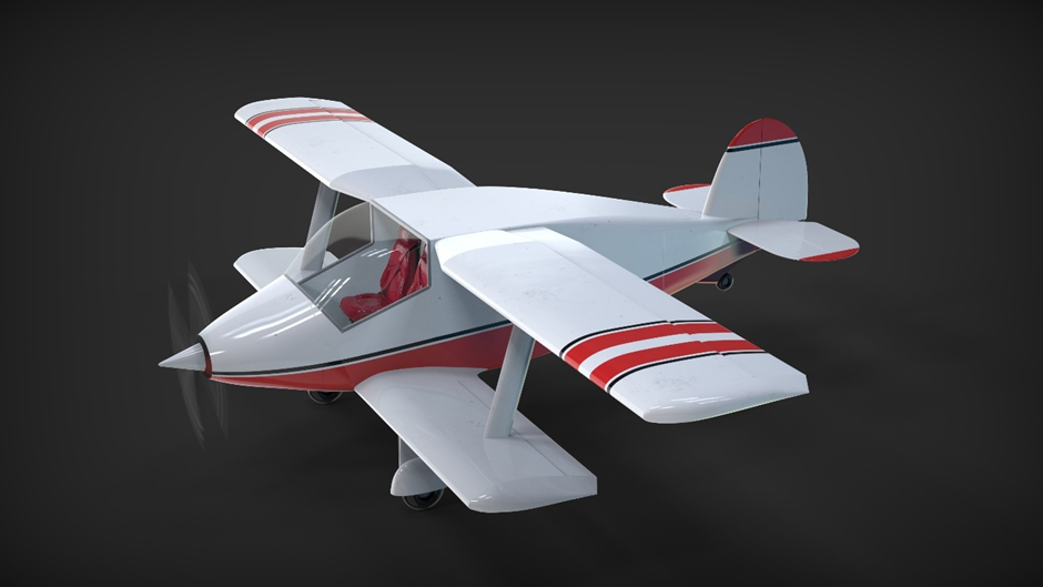
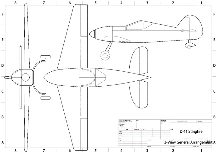
The above proposals were incorporated and the
resulting aircraft is shown in the accompanying 3-view. The name we decided on is Stingfire and it
needs no explanation.
We start with the table; the figures are self-explanatory. The types selected include the two proposals we examined. The SU 31was included to define the outer limit of current championship standards. Two well-known biplanes, the Jungmeister as the outer marker and comparatively the somewhat more sedate Tiger Moth was chosen as the standard to aim for. For the monoplane configuration we examined the French Emeraude evolved CAP 10 which has done quite well in this role, the unfortunate Victa Air Tourer and the ancient Klemm Akrobat for our study. We give below the figures for the CAP 10B for paucity of space.
|
Sl.no |
Characteristics |
D-9 Hawk Moth |
D-11 Stingfire |
Su 31 |
Bu 133 Jungmeister |
De havilland Tiger Moth |
CAP 10 Mudry |
|
1. |
Wing Span |
Upper - 8.8 m Lower – 6 m |
9.00 m |
7.80 m |
6.6 m |
8.94 m |
8.06 m |
|
2. |
Length |
6 m |
6.55 m |
6.83 m |
6 m |
7.29 m |
7.16 m |
|
3. |
Height |
2.6 m |
2.13 m |
2.76 m |
2.2 m |
2.67 m |
1.59 m |
|
4. |
Wing Area |
15.98 sq. m |
11.5 sq. m |
11.83 sq. m |
12 sq. m |
22.2 sq. m |
1.59 sq. m |
|
5. |
Engine Power kW |
135 kw |
165 kw |
300 kw |
119 kw |
97 kw |
|
|
6. |
Max. T.O weight |
1000 kg |
1000 kg |
1050 kg |
585 kg |
828 kg |
860 |
|
7. |
Aerobatic T.O. weight |
891 kg |
840 kg |
805 kg |
|
|
760 |
|
8. |
Empty weight |
791 kg |
740 kg |
700 kg |
425 kg |
506 kg |
540 |
|
9. |
Battery Weight |
536 kg |
400 kg |
|
|
|
|
|
10. |
Wing Loading |
62.57 kg/sq. m |
73 kg/sq. m |
88.75 kg/sq. m |
48.75 kg/sq. m |
37.3 kg/sq. m |
76.5 |
|
11. |
Power Loading |
7.4 kg/kw |
6.06 kg/kw |
3.5 kg/kw |
4.91 kg/kw |
8.53 kg/kw |
3.16 kg/kW |
- Better handling of the biplane specially near the stall.
- Better roll rate and turn rate of the biplane.
- Better forward view in the D-9.
- Concentration of the heaviest mass near the CG i.e., smaller radius of gyration.
- Easier production of constant chord wings.
- Better structural efficiency of the biplane allowing a higher energy battery pack of lower discharge rate.
Technical
description of the Hawkmoth Aircraft
Two seat side by side all metal aerobatic electric
sesquiplane capable of meeting the requirements of the R. Ae. Soc. 23
competition.
Fuselage
Metal box construction with minimum presswork
requirements based on the lines of Bolkow Junior or Bede 4 type aircraft.
Aluminum sheet 1mm thick sides up to the cockpit rear bulkhead, 0.8 mm thick
from rear bulkhead to rudder post. Two transverse bulkheads 1 mm thick aluminum
at firewall and cockpit rear and one frame mid-point between rear bulkhead and
rudder post. Four aluminum longerons 50 mm x 50mm x 3mm along the full length
suitably tapered after rear bulkhead to adjust with reduced loads
Wings
Constant chord NACA 2412 aerofoil with modified
rounded entry for better aerobatics. All metal light alloy construction
consisting of sheet metal 2 mm web spars with aluminum bulb section at top and
bottom. 1 mm skin covering from L.E. to main spar and 0.8 mm from there to T.E.
Sheet web ribs pitched at 40 cm spanwise. Ribs and spar webs have appropriate
lightening holes.
Empennage
PU foam Rohacell or similar empennage with metal frame
fabric covered and epoxy coated. Attached to the main fuselage structure.
Externally braced if required.
Undercarriage
Rubber in compression undercarriage with 6 x 6 tyres
for main and nose wheels with brakes on the main wheel. Undercarriage struts
are fixed to the side of the box fuselage at appropriate hard points. Lang rear
tailwheel and leaf spring shock absorber
Controls
Push rod controls operated from the cockpit. Control
runs to the rudder and elevator run from the back of the cockpit along the top
of the fuselage box to the empennage. This is covered with a foam stabilized
GRP cover for ease of adjustment, inspection, and maintenance.
Instruments
All glass Garmin G1000 Nxi or G3X cockpit with backup
for standard four instruments.
Propulsion
Battery
A quick back of the envelope calculation showed that
as a first weight budget about 536 kgs could be allocated to the battery pack
leaving a rough 250 kgs for the rest of the aircraft and 210 kgs for the pilot,
trainee, and their baggage. 536 kgs represents about 134kWh of energy or in
conventional terms about 44 liters of AvGas. That is a low figure suitable for
about a 1-hour sortie but battery capabilities are progressing from year to year.
The battery has the largest single mass and particular attention must be paid
to its location if all the benefits of electric propulsion with respect to
aerobatic handling is to be wrung out. Expectedly this will clash with the
requirements of safety, serviceability and in case of crash.
The design aim is to keep the battery as close to the
CG both vertically and longitudinally for reasons already discussed. Two
possible methods were investigated. The first was to break up the pack to four
simple thin packs externally scabbed on to the outside (Soviet style) the
advantage being simplicity and direct cooling by the slip stream for a small
penalty in drag. This was the idea used in the D-8 Zanonia the entry for 2021/22
competition. Pack housing can slide axially by 110 mm to trim
aircraft longitudinally with load sensors in the U/c struts to display settings
in the cockpit. An
alternative will be to use an internal pack with a Hunter gun pack type winch
arrangement. The pack is rapidly changeable using standard manual
foot operated fork lift hydraulic platform.
Battery configuration
The design objectives of the battery pack are rapid turnaround, flexibility in capacity, ease of handling and recharging, modularization, the ability to isolate battery issues by having sub packs and doing battery recharging away from the aircraft by solar or other ground facilities. The battery is formed by cells, preferably prismatic because of the higher surface to volume ratios and therefore better natural cooling. If we start with a nominal 120kWh battery we are looking at current levels of cell technology, a pack weight of 480kgs and a volume of 184 litres. The battery will be sub divided into subpacks of 15 kg each and the aircraft can be flown with a flexible kWh capacity in multiples of 15 i.e., 90, 105 and 120 kWh. depending on mission and pilot weight. The pack size will be W 70 cm x H 70 x L 40cm. when assembled. A Hunter gun type winch system is built in the fuselage and will be used to haul the pack up. In case of a crash landing, the battery frame will disintegrate so that the cells will be scattered and will not move en masse.
Battery Cooling
No elaborate cooling
arrangements will be made, since the battery will be drained at very low C
rates. The cells will be clipped on to a perforated sheet via long spring clips,
if you can imagine long versions of the old Meccano spring clips used to locate
stuff on the axle rods for ease of loading. These sheets, each representing a
certain number of kWh, volts would be slotted into a container much the way
various computer PCBs are located in a desktop. The battery pack will be a
series of slices, as in a toast rack with 3-5 mm gaps in between the slices to
allow for air to enter and rise in a thermosyphon effect. There will be
appropriate vents at the top and the bottom of the rack/fuselage for the
cooling air to enter and exhaust. A ground test rig will be built to prove the
efficacy of the arrangement. The accompanying sketch is self-explanatory.
Motor
EMRAX 348 motor
Battery Control and Monitoring
There are three separate
battery packs for redundancy. a. Flight Instruments, Servos Battery b. High
Power Density Battery for take-off, climb, go-around c. High Energy Density
Battery for cruise. The three batteries will feed into the Battery Management
System which will distribute power as per the flight condition and power
demand.
Propeller
Tractor fixed pitch three
bladed composite propeller, 86” diameter and 58” pitch. The Mk2 will explore
The Westland F 7/30 slow speed propeller using the step-down gear box of the
Rotax 914 at the tail and use a cardan shaft to move the motor and accessory
close to the CG for better handling.
Demonstration Flight and Performance Summary (ISA+10)

|
Empty Weight |
789 kgs |
1739 lbs. |
|
Payload |
211 kgs |
465 lbs. |
|
Aerobatic Take Off Weight |
975 kgs |
1929 lbs. |
|
Maximum Range |
395 km |
213 nautical miles |
|
Cruising Speed (KIAS@5000ft) |
203 km/h |
110 knots |
- Departure/KPDX (MSL 20 ft) – Portland International
- Take off @112kw
- Climb to 1000 ft @ 6.5 m/s and 112kw.
- Level off 1200 feet, start routine.
- Landed with 129kwh charge remaining.
- Complete aerobatic routine requires 5kwh.
- The body profile drag value of used for the Hawkmoth in the simulator is comparable with for the Cessna 172 simulator from Laminar Research, the company that makes the X-Plane product.
- Rolling co-efficient of friction = 0.025
- Airfoil data for NACA 2412 was used as included in X-Plane software without modification.
- X-Plane simulator model is running on 28V as the software does not support two buses on different voltages. Running the entire system on 650V was causing the flight instruments to consume a disproportionate amount of energy.
- Transmission loss is nil as the electric motor is used in a direct drive arrangement.
|
Wing Span |
Upper - 8.8 m Lower – 6 m |
Upper - 28.8′ Lower - 19.68 |
|
Wing Chord
|
Upper - 1.2 m Lowe – 1.0 m |
3.93′ 3.28′ |
|
Aspect Ratio (EMAR) |
5.7 |
5.7 |
|
Length Overall |
6.25 m |
20.5′ |
|
Height |
1.8 m |
3.2′ |
|
Wheel Track |
2.3 m |
7.54′ |
|
Wheel Base |
3.7 m |
12.14′ |
|
Propellor Diameter |
2.13 m |
7.00′ |
|
Clearance |
0.3 m |
11.81′′ |
|
Cockpit Length Width Height |
1.2 m 1.2 m 1.25 m |
3.93′ 3.93′ 4.10′ |
|
Wing Area |
15.98 sq. m |
172 sq. ft |
|
Aileron Area |
1.28 sq. m |
10.76 sq. ft |
|
Fin Area |
1.28 sq. m |
13.78 sq. ft |
|
Rudder Area |
0.64 sq. m |
6.89 sq. ft |
|
Weight Empty without Battery |
253 kg |
558 lbs. |
|
Weight Empty with Battery |
789 kg |
1739 lbs. |
|
Payload |
211 kg |
465 lbs. |
|
Max Take Off (MTO) |
1000 kg |
1322.77 lbs. |
|
Wing Loading @ MTO |
62.57 kg/sq. m |
8.92 lbs./sq. ft |
|
Power Loading @ MTO |
7.4 kg/kw @ peak torque |
12.18 lb./hp |
|
|
96 kmph |
59.67 mph |
|
|
115.24 kmph |
71.61 mph |
|
|
219 kmph |
136 mph |
|
|
283 kmph |
176 mph |
|
Climb |
8.47 m/s |
1667 feet/min |
|
Range @MTO |
345 km with 20% reserve |
214 miles with 20% reserve |
|
Maximum Range |
395 km with 20% reserve |
245 miles with 20% reserve |
|
T.O Run from paved runway |
203 m |
666 feet |
|
Landing Distance |
365 m |
1197.5 feet |
Comments
Post a Comment